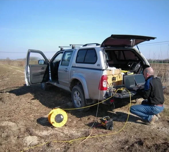
The seismic tomography setup we mobilize to Medicine Hat starts with a 48-channel seismograph paired with 4.5 Hz geophones spaced across spreads up to 230 meters. For shallow refraction work, a 10 kg sledgehammer source delivers the energy needed to image the first 20 to 30 meters—plenty of resolution to map the Cretaceous Bearpaw Formation shale and overlying glacial till that define the subsurface across the South Saskatchewan River valley. When the project demands deeper reflection profiles—say, for a proposed mid-rise on the flats near the Gas City Campground—we switch to an accelerated weight drop source that punches clean signal down to 80 meters and beyond. The entire spread cables up in under 40 minutes, meaning we can acquire multiple lines in a single day even with Medicine Hat’s afternoon winds picking up across the coulee terrain.
Interpreting those travel-time curves is where the real value sits. We model P-wave velocity gradients layer by layer, and because the till-to-shale contact in this region typically shows a velocity jump from roughly 1,600 m/s to over 2,800 m/s, the refraction break is unambiguous. For projects where the overburden is thin and bedrock rippability is the question, we often pair the tomography with a CPT test to calibrate velocity against tip resistance, giving the excavation contractor a single coherent ground model instead of two separate reports that may not agree at the boundaries.
A refraction P-wave velocity jump from 1,600 to 2,800 m/s across the till-shale contact in Medicine Hat gives an unambiguous bedrock surface within ±0.5 meters.
Our approach and scope
For foundation designers working in the river valley where paleochannel sands and gravels can lens unpredictably, the velocity cross-section from a refraction line often reveals these features before a single borehole is drilled. When we see a low-velocity pocket of 900 to 1,200 m/s sitting inside stiffer till, that is usually a sand lens that warrants a targeted SPT drilling to confirm density and liquefaction susceptibility under the NBCC 2020 seismic provisions for southeastern Alberta.
Local considerations
Medicine Hat’s built footprint expanded rapidly after the 1908 gas boom, and many pre-1960 structures in the Flats and River Heights neighborhoods were founded on spread footings bearing directly on glacial till without a systematic understanding of the bedrock profile beneath. The risk today is inherited: when a developer proposes an addition or a heavy retrofit on one of these older parcels, the assumption that shallow till is uniform can be dangerously wrong. Buried channels carved into the Bearpaw shale during glacial retreat—some 15 to 20 meters deep and backfilled with soft, normally consolidated silts—hide beneath what looks like competent ground. A refraction tomography line run diagonally across the lot will flag those channels as a sharp velocity reversal that no amount of hand-augering would catch. Skipping this step has led to differential settlement claims in the city, particularly where new three- and four-storey wood-frame condominiums were placed adjacent to century-old brick walk-ups with very different foundation stiffnesses.
Reference standards
NBCC 2020 (National Building Code of Canada, seismic provisions for Alberta), CSA A23.3-19 (Design of concrete structures, foundation references), ASTM D5777-18 (Standard Guide for Using the Seismic Refraction Method), ASTM D7128-18 (Standard Guide for Using the Seismic Reflection Method)
Complementary services
Seismic refraction tomography for bedrock mapping and rippability
Designed for projects where the depth to shale bedrock dictates excavation method and foundation type. We acquire overlapping refraction spreads with hammer and weight-drop sources, invert the travel-time data using a gradient-based tomographic algorithm, and deliver a continuous 2D velocity cross-section annotated with interpreted till-shale boundaries. The velocity model is calibrated against local borehole data to ensure the rippability classification—marginal versus non-rippable for a D9 dozer—is reliable. This configuration is standard for commercial pads in the Brier Park and Box Springs industrial areas.
High-resolution seismic reflection for deep stratigraphic imaging
Applied when the target is deeper than 40 meters or when thin stratigraphic units within the drift need to be resolved—for example, mapping a confined gravel aquifer beneath a proposed deep excavation near the river. We use a 24-geophone array with single-sensor recording, an accelerated weight drop for repeatable signature, and full CDP processing including NMO correction, surface-consistent deconvolution, and post-stack migration. The result is a reflectivity section that ties directly to borehole stratigraphy and can be used to plan dewatering or cutoff wall depths.
Typical parameters
Common questions
What does a seismic tomography survey cost for a typical Medicine Hat commercial lot?
For a standard commercial lot investigation in Medicine Hat—typically two to three refraction lines totaling 300 to 500 lineal meters—the cost ranges from CA$4,030 to CA$7,480, depending on line length, source type (hammer versus weight drop), and whether reflection processing is added. A site visit to assess access and ground conditions lets us provide a fixed-price proposal rather than an estimate.
How deep can you see with refraction versus reflection in the drift around Medicine Hat?
Refraction reliably images the top 20 to 30 meters, which covers the full drift thickness across most of the city and resolves the bedrock contact clearly. Reflection extends the investigation depth to 60 meters and deeper, and is the preferred method when we need to identify internal stratigraphy—sand lenses, gravel channels, or water-bearing zones—that refraction alone may not resolve because of velocity inversions within the till.
Do you need boreholes to calibrate the seismic velocities?
The reference range for this service in Medicine Hat is CA$4.030 - CA$7.480. The final price depends on the project scope and volume.